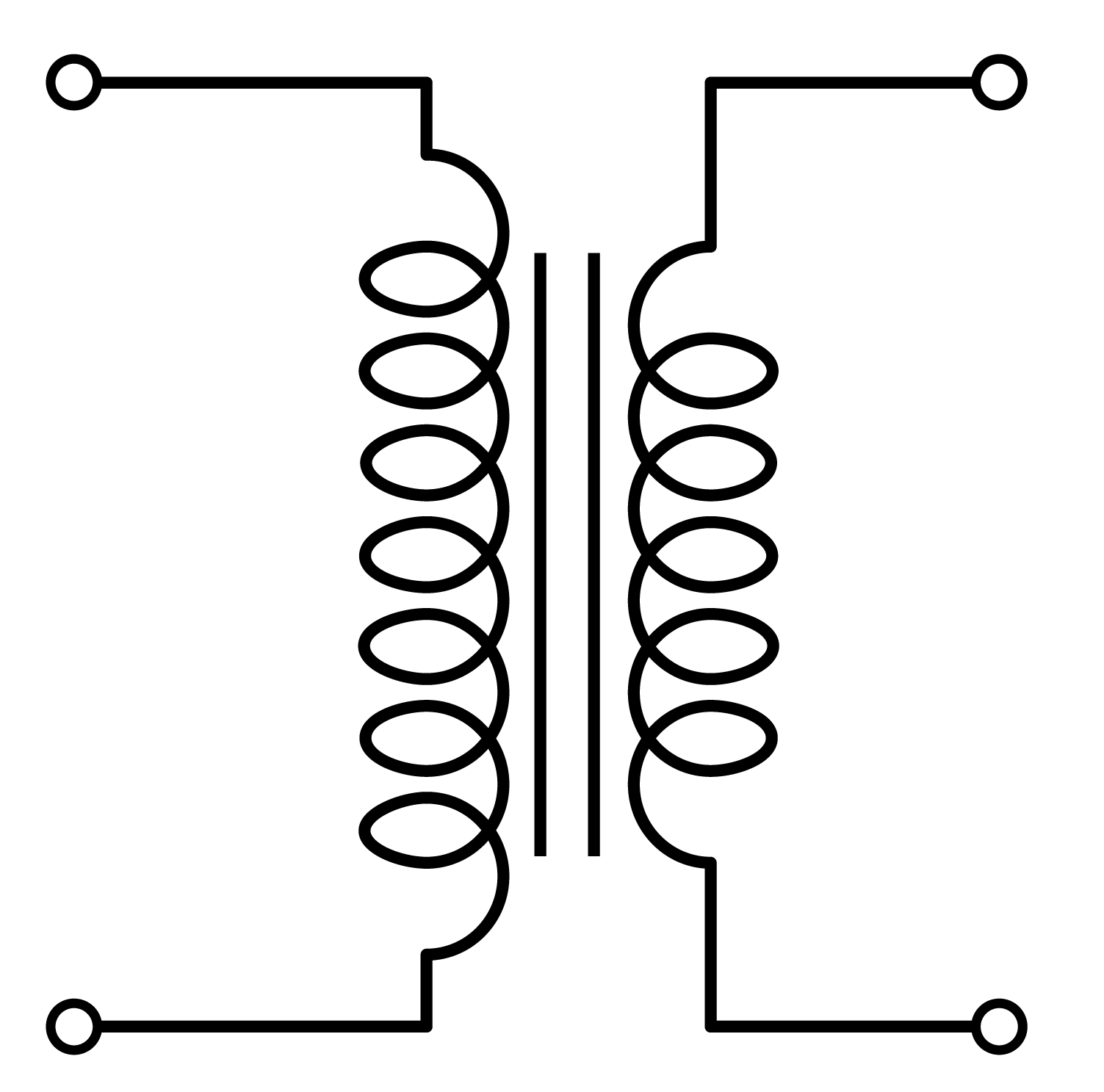
Understanding Current Transformer Symbols

Have you ever looked at an electrical diagram and wondered about those cryptic symbols? Understanding these symbols is crucial, especially when dealing with current transformers (CTs). This article explores the world of current transformer symbols, delving into their meaning, history, and practical applications.
A current transformer symbol represents a device that measures current indirectly. It's a simplified representation used in circuit diagrams to indicate the presence and function of a CT. These symbols allow engineers and technicians to quickly grasp the overall circuit configuration without needing to see the physical device. Think of it as a shorthand for complex electrical components.
Current transformer graphical representations have evolved over time. Early diagrams might have used more detailed drawings, but as electrical engineering progressed, the need for simpler, standardized symbols became apparent. The current transformer icon we see today is a result of this evolution, designed for clarity and efficiency.
The importance of standardized current transformer representation cannot be overstated. It allows for universal understanding among electrical professionals, regardless of their language or background. This visual language is essential for collaboration, design, and troubleshooting in electrical systems.
One of the main challenges with current transformer symbology is ensuring everyone involved understands the nuances of different symbol variations. Some symbols might indicate specific CT types, such as those for protection or metering. Misinterpreting these symbols can lead to errors in circuit design and operation.
A basic current transformer diagram symbol typically consists of two coils, one representing the primary winding and the other the secondary winding. The primary winding is usually shown as a thick line or a rectangle, while the secondary is a thinner line. Often, the ratio of the primary to secondary turns is indicated within the symbol.
Understanding the current transformer polarity marking is also crucial. This marking indicates the relative direction of current flow in the primary and secondary windings. Correctly interpreting polarity is essential for proper metering and protection relay operation.
One benefit of standardized current transformer representation is improved communication in design and troubleshooting. Clear symbols minimize ambiguity, ensuring everyone is on the same page.
Another advantage is enhanced safety. Properly understanding CT symbols helps ensure correct installation and operation, reducing the risk of accidents and equipment damage.
A third benefit is efficient circuit analysis. Recognizable symbols allow engineers to quickly analyze circuits and identify potential issues.
One best practice is to consult relevant standards for the correct current transformer graphic symbol usage. This ensures consistency and clarity in your diagrams.
Another practice is to clearly label all current transformer designators in your diagrams. This makes it easy to identify specific CTs and their corresponding parameters.
Advantages and Disadvantages of Standardized CT Symbols
| Advantages | Disadvantages |
|---|---|
| Clear communication | Potential for misinterpretation if not standardized |
| Enhanced safety | Variations in symbols can create confusion |
| Efficient circuit analysis | Requires training to understand all variations |
Frequently Asked Questions:
1. What does a CT symbol look like? - Typically two coils, one thicker than the other.
2. Why are CT symbols important? - They provide a standardized way to represent CTs in diagrams.
3. How do I identify CT polarity from the symbol? - Look for polarity markings near the terminals.
4. Where can I find more information about CT symbols? - Consult relevant electrical standards and textbooks.
5. What are some common variations of CT symbols? - Variations may indicate specific CT types like protection or metering CTs.
6. Are there different symbols for different CT ratios? - The ratio is usually indicated within or near the symbol.
7. What is the significance of the dotted line in some CT symbols? - It often represents the secondary winding.
8. How can I improve my understanding of CT symbols? - Study electrical diagrams and consult relevant resources.
In conclusion, understanding current transformer symbols is fundamental for anyone working with electrical systems. From design and installation to troubleshooting and maintenance, these symbols play a critical role in ensuring safety and efficiency. By familiarizing yourself with the different symbol variations and best practices for their use, you can enhance your understanding of electrical diagrams and contribute to more effective electrical system management. Embrace these symbols as an essential tool in your electrical engineering toolkit, and you'll find yourself navigating complex circuits with greater confidence and clarity. Mastering the language of electrical diagrams, including CT symbols, empowers you to communicate effectively with other professionals and contribute to safer, more reliable electrical systems. This knowledge is not merely a technical skill but a key to unlocking greater efficiency and confidence in your work.
Farrow and ball danmark transforming danish homes
Toasted almond paint sherwin williams warm neutral guide
Discover the magic of khao sok national park


