Mastering Pneumatic Symbols: A Comprehensive Guide

Imagine a complex network of tubes, valves, and actuators working seamlessly together to power automated machinery. This intricate dance is orchestrated by pneumatic systems, and at the heart of understanding these systems lies a language of symbols: pneumatic symbols. These graphical representations are crucial for designing, interpreting, and troubleshooting pneumatic circuits. This guide delves into the world of commonly used pneumatic symbols, equipping you with the knowledge to navigate this essential aspect of pneumatic technology.
Understanding pneumatic diagrams is fundamental for anyone working with pneumatic equipment. Whether you're a maintenance technician, an engineer, or a student, grasping the meaning of these symbols allows you to decipher the function and interaction of various components within a pneumatic system. From simple directional control valves to complex logic circuits, the language of pneumatic symbols provides a universal method of communication, bridging the gap between design and implementation.
Pneumatic symbols are standardized graphical representations of pneumatic components. They depict the function of each component and how they connect within a circuit. These symbols are standardized by ISO 1219-1, ensuring consistency and clarity across different industries and geographical locations. This standardization facilitates effective communication and collaboration among engineers and technicians worldwide. The symbols, typically depicted in a simplified, schematic form, abstract away the physical complexities of the components, allowing for a clearer understanding of the system's logic and operation.
The history of pneumatic symbols is intertwined with the development of pneumatic technology itself. As pneumatic systems became more complex, the need for a standardized representation arose. Early pneumatic diagrams often utilized rudimentary sketches or manufacturer-specific symbols, leading to confusion and misinterpretations. The adoption of ISO standards brought much-needed clarity and consistency to the field. This standardization greatly improved the efficiency of designing, building, and maintaining pneumatic systems. It also enabled the sharing of pneumatic circuit designs across different teams and companies without ambiguity.
The primary function of pneumatic symbols is to provide a clear and concise representation of a pneumatic circuit. They offer a visual roadmap of the system, detailing the flow of compressed air, the function of each component, and the overall logic of the operation. Without these symbols, understanding and troubleshooting a complex pneumatic system would be incredibly challenging, like navigating a city without a map. They are indispensable for design, installation, maintenance, and troubleshooting of any pneumatic equipment.
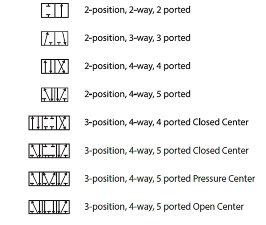
A simple example is the symbol for a directional control valve. A box with arrows indicates the flow path of air depending on the valve's position. Different variations of this symbol represent different valve types, such as 2/2 valves, 3/2 valves, and 5/2 valves, each with its specific functionality.
One of the primary benefits of using standardized pneumatic symbols is improved communication. Engineers and technicians from different backgrounds can easily understand a pneumatic diagram regardless of language barriers. This simplifies collaboration and reduces the risk of errors due to miscommunication. Clear communication also ensures that maintenance procedures are understood and executed correctly, reducing downtime and improving overall system reliability.
Another key advantage is enhanced troubleshooting capabilities. By referencing the pneumatic diagram, technicians can quickly identify the source of a problem within the system. This reduces diagnostic time and allows for faster repairs. Faster troubleshooting minimizes downtime, which is crucial for maintaining productivity in any industrial setting.
Lastly, the use of these symbols simplifies the design process. Engineers can quickly and efficiently lay out a pneumatic circuit using standard symbols, enabling them to test different configurations and optimize the system's performance before physical implementation. This streamlines the design process and reduces development time, ultimately contributing to cost savings.
Advantages and Disadvantages of Standardized Pneumatic Symbols
While standardized symbols offer significant advantages, understanding some potential drawbacks is essential.
| Advantages | Disadvantages |
|---|---|
| Clear Communication | Requires Training |
| Efficient Troubleshooting | Potential for Misinterpretation if not used correctly |
| Simplified Design Process | Can be Complex for Highly Intricate Systems |
Implementing standardized pneumatic symbols requires a systematic approach. Ensure adherence to ISO 1219-1, providing training to all personnel involved in designing, operating, and maintaining pneumatic systems. Use software tools that support these standards for efficient circuit design and documentation.
A real-world example is the use of pneumatic symbols in the automotive industry for controlling robotic arms in assembly lines. These symbols are used to design and troubleshoot the complex pneumatic circuits that control the precise movements of these robots.
Frequently Asked Questions about pneumatic symbols are often related to understanding specific symbols, their variations, and their application in different circuits.
One tip for working with pneumatic symbols is to always refer to the ISO 1219-1 standard for clarification and consistency. This ensures that everyone is on the same page and reduces the risk of misinterpretations.
In conclusion, commonly used pneumatic symbols are the cornerstone of effective pneumatic system design, operation, and maintenance. They provide a universal language for understanding complex circuits, facilitating clear communication, efficient troubleshooting, and streamlined design processes. By mastering these symbols, professionals in various industries can unlock the full potential of pneumatic technology, optimizing performance, minimizing downtime, and driving efficiency in countless applications. From simple actuators to complex automated systems, the understanding and proper application of these symbols is paramount for anyone working with pneumatic equipment. Embrace the language of pneumatics and unlock the power of efficient and reliable automated systems. Investing time and resources in learning and implementing these standards will undoubtedly lead to improved productivity, reduced errors, and a safer working environment.
William burke stony brook ny a comprehensive overview
Aesthetic t shirt photos capturing the essence of style
The enchanting play of sun and moon games


