Decoding the Secrets of Electronic Component Symbols

Imagine you're an archaeologist stumbling upon an ancient scroll. Covered in strange markings, it holds the secrets to a lost civilization. That's kind of what it feels like delving into the world of electronics without understanding electronic component symbols. These symbols, like hieroglyphs of the electrical realm, are the fundamental language of circuit diagrams.
So, what exactly are these cryptic symbols? They're visual representations of electronic components, like resistors, capacitors, transistors, and integrated circuits. They're standardized so engineers across the globe can understand the function and connections within a circuit without needing lengthy descriptions. Think of them as the universal language for designing, building, and troubleshooting electronic systems.
Why is understanding these symbols so crucial? Well, without them, the world of electronics becomes a chaotic jumble of wires and components. Imagine trying to build a complex LEGO structure without knowing what each brick represents. Similarly, electronic component symbols provide the blueprint for understanding and constructing any electronic circuit, from simple LED circuits to complex microprocessors.
This guide aims to unravel the mysteries of electronic component symbols, taking you from a complete novice to a more confident navigator of the electronic landscape. We'll explore their history, delve into their importance, and provide practical examples to solidify your understanding.
So, let's embark on this electrifying journey, deciphering the language of circuits and unlocking the power of electronic component symbols.
The use of standardized electronic symbols emerged alongside the rapid development of electronics in the early to mid-20th century. As circuits became more complex, the need for a clear and concise way to represent components became paramount. Various organizations, including the Institute of Electrical and Electronics Engineers (IEEE) and the International Electrotechnical Commission (IEC), played a key role in establishing these standards.
These standardized symbols are essential for efficient communication among engineers, technicians, and hobbyists. They ensure that everyone is on the same page, minimizing errors and facilitating collaboration in the design and analysis of electronic systems.
One of the primary issues related to electronic component symbols is the occasional variation in representation across different standards or regions. While efforts are made to maintain consistency, some discrepancies can exist, requiring careful attention to the specific standard being used.
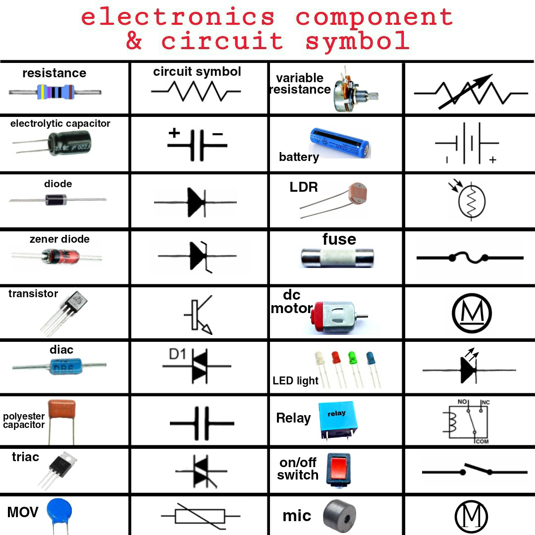
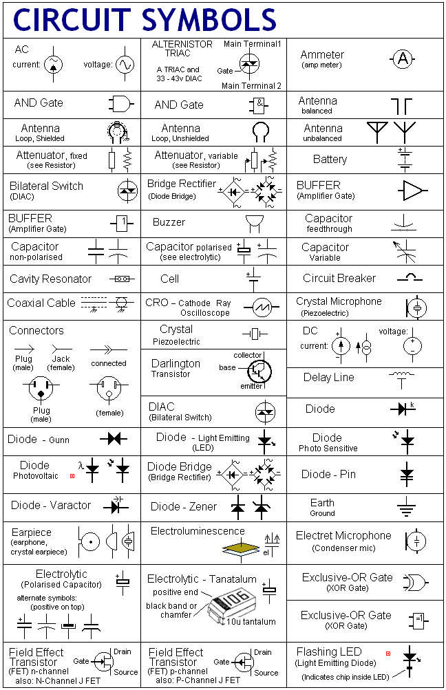
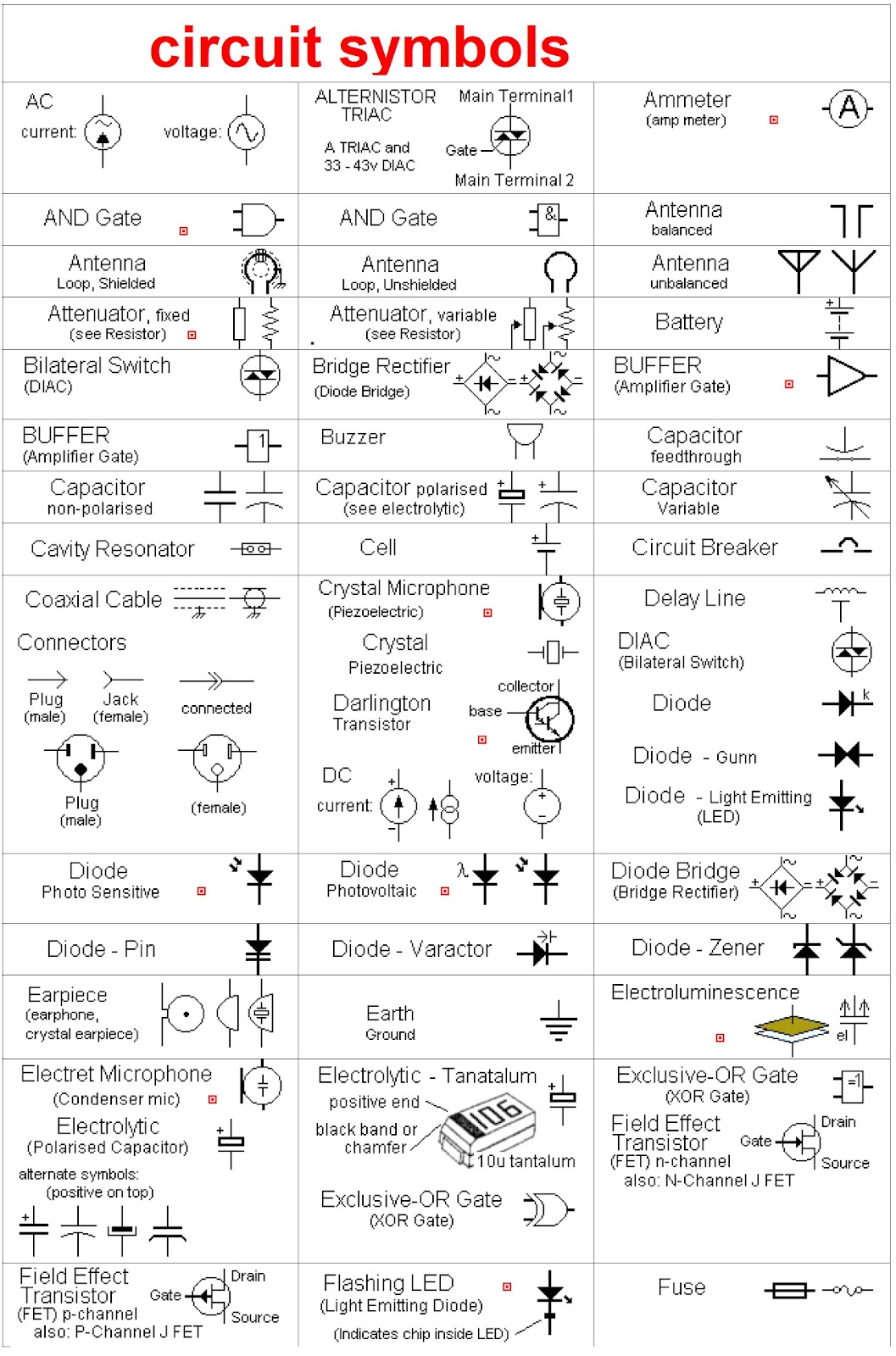
A resistor, for example, is represented by a zig-zag line. A capacitor is often represented by two parallel lines. A diode, which allows current to flow in only one direction, is shown as a triangle with a line across one end. These are just a few basic examples, and there are numerous other symbols representing a wide range of components.
Benefits of using standardized electronic component symbols include: 1. Clear Communication: They facilitate unambiguous understanding of circuit diagrams. 2. Simplified Design: They enable efficient design and analysis of electronic systems. 3. Reduced Errors: They minimize the risk of misinterpretations and errors during circuit construction.
For example, understanding the symbol for a transistor allows you to quickly identify its type (NPN or PNP) and its connections within the circuit. This helps in analyzing how the transistor will function within the overall system.
Advantages and Disadvantages of Standardized Symbols
| Advantages | Disadvantages |
|---|---|
| Clear Communication | Potential variations across standards |
| Simplified Design | Requires learning and memorization |
| Reduced Errors |
Best practices for using electronic component symbols include adhering to a recognized standard (like IEEE or IEC), ensuring consistent usage across all documentation, and providing a legend or key when using less common symbols.
Real-world examples of electronic component symbols can be found in any circuit diagram, from the schematic of a simple radio to the blueprint of a complex computer motherboard.
A challenge in using these symbols can be the sheer number and variety. A solution is to use reference charts and software tools that provide easy access to symbol libraries.
FAQ: 1. Where can I find a comprehensive electronic component symbols chart? Answer: Many resources are available online and in textbooks. 2. What is the symbol for a diode? Answer: A triangle with a line. 3. Are electronic symbols standardized globally? Answer: Largely, yes, but some variations might exist.
A helpful tip is to start by learning the symbols for the most common components and gradually expanding your knowledge.
In conclusion, electronic component symbols are the foundational language of electronics. Understanding these symbols is paramount for anyone involved in designing, building, or troubleshooting electronic systems. Mastering this language opens doors to a world of innovation and allows you to communicate effectively with other engineers and enthusiasts. From simple circuits to complex systems, these symbols are the key to unlocking the power and potential of electronics. Take the time to study them, familiarize yourself with their meanings, and explore the vast resources available. Your journey into the fascinating world of electronics starts with understanding these fundamental building blocks.
Unveiling the enigma exploring the impact of dr law ping man
Unlocking calhoun county treasures facebook marketplace
Decoding the allure of pull up on me songs

.jpg)


