Decoding Jog Motor Control Wiring Diagrams

Ever wondered how industrial machines achieve that pinpoint precision in movement? Or how robotics achieve such fluid, controlled motion? The secret often lies within a seemingly simple yet powerful tool: the jog motor control circuit diagram. These blueprints dictate the intricate dance of electrons that empower precise, incremental motor movements, vital for countless applications.
Jog control, in essence, allows for controlled, short bursts of motor movement, ideal for precise positioning or testing. The schematic for this control acts as the Rosetta Stone, translating the desired functionality into a tangible circuit design. Understanding these diagrams is crucial for anyone working with automated systems, from factory automation engineers to robotics enthusiasts.
The evolution of motor control schematics mirrors the advancement of control systems themselves. Early systems relied on cumbersome mechanical switches and relays. Today, sophisticated microcontrollers and programmable logic controllers (PLCs) dominate the landscape, enabling complex control algorithms and enhanced flexibility. The underlying principle, however, remains the same: a visual representation guiding the connection of components to achieve precise motor control.
Jog motor control diagrams are indispensable for troubleshooting, maintenance, and system upgrades. They serve as a visual guide, allowing technicians to quickly identify components, trace connections, and diagnose faults. This visual clarity drastically reduces downtime and improves overall system reliability.
One of the key challenges in designing jog control circuits is ensuring safety. Implementing appropriate safety measures, such as emergency stops and limit switches, is paramount. The schematic diagram becomes a crucial tool for verifying the implementation of these safety features, ensuring both operator safety and equipment protection.
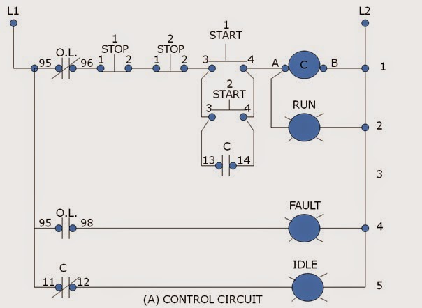
A basic jog control circuit often involves a momentary push button switch, a motor starter, and the motor itself. When the button is pressed, the motor starter is energized, powering the motor. Releasing the button de-energizes the starter, stopping the motor. More complex systems might incorporate direction control, speed regulation, and feedback mechanisms, all meticulously detailed in the schematic.
Three key benefits of using a well-designed schematic are: enhanced troubleshooting (quickly identify faulty components), improved communication (a universal language for technicians), and streamlined design (facilitates efficient circuit layout and component selection).
A step-by-step guide for creating a basic jog control schematic might involve: 1. Defining the motor specifications. 2. Selecting appropriate control components. 3. Drawing the circuit, including safety features. 4. Simulating the circuit operation. 5. Implementing and testing the physical circuit.
Advantages and Disadvantages of Using Schematic Diagrams
| Advantages | Disadvantages |
|---|---|
| Clear Visualization | Can become complex for large systems |
| Simplified Troubleshooting | Requires specialized knowledge to interpret |
| Improved Communication | Static representation, doesn't show real-time data |
Best Practices: 1. Use standardized symbols. 2. Clearly label all components. 3. Implement safety features. 4. Document revisions. 5. Verify the diagram against the physical circuit.
Real-World Examples: CNC machines, robotic arms, conveyor belts, automated packaging systems, and 3D printers all utilize jog motor control for precise positioning.
Challenges and Solutions: Dealing with noise interference (use shielded cables), component failure (implement redundancy), and software integration (ensure compatibility). Addressing these challenges proactively is key to a robust and reliable system.
FAQs: What is jog control? What components are needed? How does a jog control circuit work? How do I troubleshoot a jog control circuit? What are the safety considerations? How do I choose the right components? How can I improve the efficiency of my jog control system? What are the latest trends in jog motor control technology?
Tips and tricks: Use simulation software to test your design, always double-check your connections, and keep your schematics up-to-date.
In conclusion, the schematic diagram of a jog motor control system is more than just lines and symbols; it's the blueprint for precise, controlled motion in countless applications. Mastering these diagrams is essential for anyone working with automated systems. From simplifying troubleshooting to enabling complex control algorithms, the schematic diagram is the key to unlocking the full potential of jog motor control. By understanding the principles, best practices, and challenges associated with these diagrams, engineers and technicians can design, implement, and maintain robust, efficient, and safe motor control systems. Embrace the power of the schematic, and witness the seamless integration of motion into your automated world. This knowledge empowers you to optimize performance, enhance safety, and drive innovation in the ever-evolving landscape of automation technology. Don't just control motion, master it.
Effortless drifting exploring the minn kota 24 lb thrust trolling motor
Saying stella artois a guide to pronouncing the belgian brew
Unlocking summer adventures family travel destinations


