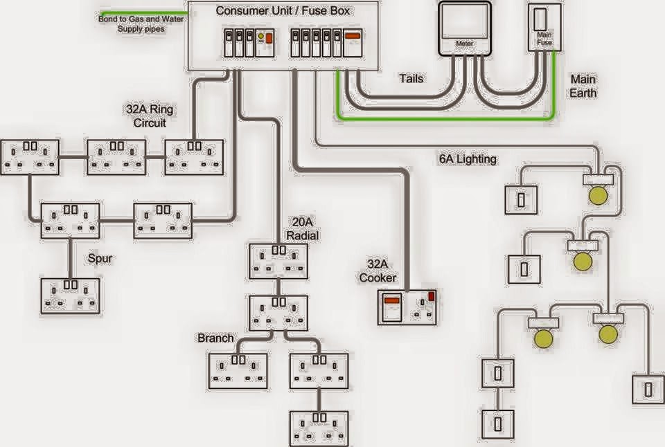
Decoding Electrical Blueprints: A Guide to Electrical Plan Symbols

Imagine stepping onto a construction site, a symphony of activity unfolding before you. Amidst the controlled chaos, blueprints serve as the conductor's score, guiding every action. But what about those enigmatic symbols scattered across the electrical plans? These seemingly cryptic markings are the language of electricians, a vital shorthand that dictates the placement of every outlet, switch, and wire. Understanding these typical electrical plan symbols is essential for anyone involved in building or renovating a space, from architects and engineers to contractors and homeowners.
Electrical plan symbols are visual representations of electrical components and their connections within a building's electrical system. They provide a concise and standardized way to communicate the design intent, ensuring that everyone involved in the project is on the same page. This shared understanding minimizes errors, streamlines the construction process, and ultimately leads to a safer and more functional electrical system.
The history of electrical plan symbols is intertwined with the development of electrical engineering itself. As electrical systems became more complex, the need for a standardized visual language became apparent. Over time, these symbols evolved, becoming more refined and encompassing a wider range of electrical devices and functionalities. Organizations like the National Electrical Manufacturers Association (NEMA) and the International Electrotechnical Commission (IEC) have played a crucial role in standardizing these symbols, promoting consistency and clarity across different regions and industries.
The importance of correctly interpreting electrical plan symbols cannot be overstated. Misinterpretations can lead to costly mistakes, delays in construction, and potentially hazardous electrical installations. Imagine a scenario where a symbol for a light switch is mistaken for an outlet. This seemingly minor error could result in an improperly wired circuit, creating a fire hazard or rendering the lighting system non-functional.
One of the main issues surrounding electrical plan symbols is the potential for variations and regional differences. While standardization efforts have greatly reduced this problem, it's important to be aware that certain symbols might have slightly different meanings depending on the specific context or geographical location. Consulting relevant electrical codes and standards is crucial for ensuring accurate interpretation and implementation of electrical plans.
A simple example is the symbol for a duplex receptacle (standard electrical outlet). It's typically represented by a circle with two short vertical lines extending from it. This simple symbol clearly communicates the location and type of electrical device, allowing electricians to install it correctly.
Benefits of using standardized electrical plan symbols include: improved communication among project stakeholders, reduced errors in electrical installations, and enhanced safety by ensuring consistent and accurate wiring practices.
An action plan for working with electrical symbols involves: familiarizing yourself with common symbols, referencing relevant electrical codes and standards, and consulting with experienced electricians when necessary.
Advantages and Disadvantages of Standardized Electrical Symbols
| Advantages | Disadvantages |
|---|---|
| Clear Communication | Potential for Regional Variations |
| Reduced Errors | Requires Training and Familiarity |
| Enhanced Safety | Can be Complex for Large Systems |
Best practices include using clear and legible symbols, adhering to industry standards, and providing a legend to explain any non-standard or custom symbols.
Real-world examples of electrical plan symbols in action can be found in residential wiring diagrams, commercial building plans, and industrial electrical schematics.
Challenges related to electrical symbols can include keeping up with evolving standards and ensuring accurate interpretation of complex diagrams. Solutions involve continuous education and consultation with experts.
FAQs: What is the symbol for a light switch? What does a dotted line on an electrical plan represent? What is the difference between a single-pole and a three-way switch symbol?
Tips and tricks: Use a symbol library for quick reference. Consult with experienced electricians for clarification on complex symbols.
In conclusion, understanding typical electrical plan symbols is paramount for anyone involved in building or renovation projects. These symbols form the backbone of effective communication in electrical design, ensuring accuracy, safety, and efficiency throughout the construction process. From the initial design stages to the final inspection, these symbols play a vital role in bringing electrical systems to life. By familiarizing yourself with these symbols, adhering to industry standards, and embracing best practices, you can contribute to creating functional, safe, and code-compliant electrical installations. The power of clear communication through electrical plan symbols truly illuminates the path to a successful project. Take the time to learn these symbols—it's an investment that pays dividends in safety, efficiency, and peace of mind.
Dominate the flank unleashing fifa 23s top left backs
Biomedical science bachelors at usm a glimpse into malaysias cutting edge program
St michael archangel forearm tattoo deep dive


