Decoding Diode Symbols: A Comprehensive Guide

Ever stared at a circuit diagram and felt a twinge of confusion when encountering a triangle with a line? That's a diode, a fundamental component in electronics. But did you know that this seemingly simple component comes with a variety of schematic symbols, each carrying subtle but crucial information? Understanding these variations is essential for any aspiring electronics enthusiast or seasoned professional.
Diode symbols aren't merely arbitrary shapes. They're a visual language that communicates the diode's function and characteristics. Different diodes serve different purposes, and their symbols reflect these distinct roles. This guide delves into the world of diode schematic symbols, exploring their history, significance, and practical implications. We'll decode the secrets hidden within these symbols, empowering you to navigate circuit diagrams with confidence and precision.
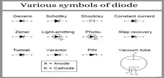
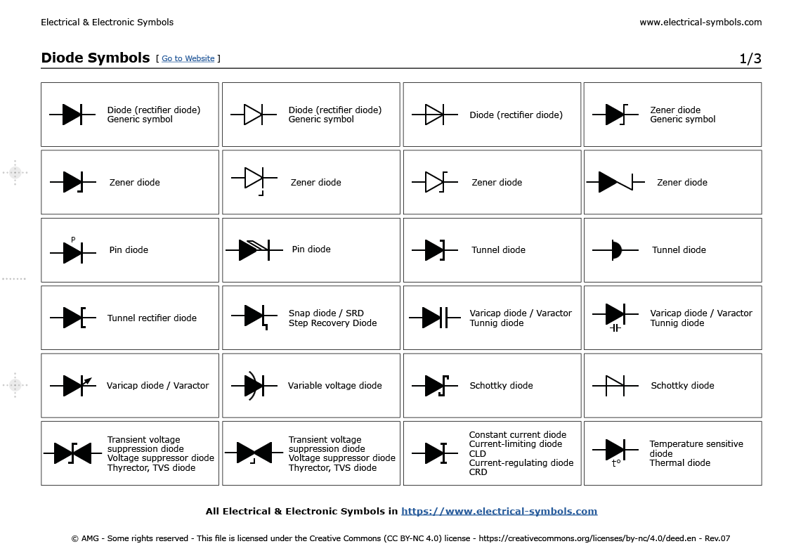
The most basic diode symbol is the arrow pointing towards a line. This represents the fundamental unidirectional flow of current allowed by a diode. However, as technology progressed, so did the need for diodes with specialized functionalities. This led to the development of various diode types, each with its own unique symbol. Schottky diodes, Zener diodes, light-emitting diodes (LEDs), and photodiodes are just a few examples. Recognizing these symbols is key to understanding the circuit's behavior and purpose.
The historical evolution of diode symbols mirrors the advancement of diode technology itself. Early diode symbols were often simplistic, evolving over time to incorporate more nuanced representations. This development reflects the increasing complexity and specialization of diode applications. Understanding this historical context provides valuable insights into the logic behind the symbols we use today.
The importance of correctly interpreting diode symbols cannot be overstated. Misinterpreting a symbol can lead to circuit malfunctions, incorrect analysis, and potentially even damage to components. This highlights the need for a comprehensive understanding of diode schematic variations. Mastering these visual cues is a crucial step in effectively designing, analyzing, and troubleshooting electronic circuits.
The earliest diodes were vacuum tubes, and their schematic symbols reflected their physical structure. With the advent of semiconductor diodes, the symbols transitioned to more abstract representations. The arrow and bar symbolize the unidirectional current flow characteristic of diodes, mirroring the anode and cathode structure. Different diode types then added further modifications to this basic symbol, reflecting their specific functionality.
Let's illustrate with an example: a Zener diode. Its symbol features a 'Z' shaped bend in the bar, visually hinting at its voltage regulation capabilities. This distinctive mark differentiates it from a standard rectifier diode. Similarly, an LED's symbol incorporates arrows pointing outwards, signifying light emission.
One of the main issues surrounding diode schematic symbols is the potential for confusion between different types. For instance, a novice might misinterpret a Schottky diode symbol for a standard diode, leading to inaccurate circuit analysis. This underscores the importance of careful study and practice in correctly identifying diode symbols.
Benefits of understanding different diode symbols include: improved circuit analysis, accurate component selection, and enhanced troubleshooting abilities. For example, knowing the symbol for a varactor diode (which uses two parallel lines instead of one for the bar) allows you to quickly identify its role as a voltage-controlled capacitor in a circuit.
Advantages and Disadvantages of Standardized Diode Symbols
| Advantages | Disadvantages |
|---|---|
| Universal understanding across engineers | Can be overwhelming for beginners due to sheer variety |
| Facilitates efficient communication and collaboration | Subtle variations can be easily missed, leading to errors |
Best Practices:
1. Consult datasheets: Always refer to component datasheets for precise symbol definitions.
2. Use simulation software: Simulate circuits to verify symbol interpretation and functionality.
3. Practice reading complex diagrams: Regularly analyze complex schematics to enhance symbol recognition.
4. Cross-reference multiple sources: Compare symbols from different textbooks and online resources.
5. Seek expert advice when uncertain: Consult experienced engineers for clarification on ambiguous symbols.
FAQ:
1. What does the arrow in a diode symbol represent? (Direction of conventional current flow)
2. How does a Zener diode symbol differ from a regular diode? (Z-shaped bend in the bar)
3. What do the outward arrows in an LED symbol signify? (Light emission)
4. What is the significance of the double bar in a varactor diode symbol? (Voltage-controlled capacitance)
5. Why is it important to correctly identify diode symbols? (Accurate circuit analysis and troubleshooting)
6. Where can I find reliable information on diode symbols? (Datasheets, textbooks, online resources)
7. How can I improve my ability to recognize different diode symbols? (Practice and cross-referencing)
8. What are some common mistakes to avoid when interpreting diode symbols? (Confusing similar symbols)
In conclusion, mastering the language of diode schematic symbols is an essential skill for anyone working with electronics. From the basic rectifier diode to specialized components like Zener diodes and LEDs, each symbol tells a story about the diode's function and characteristics. By understanding these symbols, we can accurately interpret circuit diagrams, design effective electronic systems, and troubleshoot problems efficiently. The benefits of this knowledge extend beyond technical proficiency, empowering us to engage with the intricate world of electronics with greater confidence and precision. Take the time to study and practice, and you'll unlock a deeper understanding of circuit behavior and the crucial role played by these seemingly simple symbols. Don't hesitate to explore further resources, consult datasheets, and engage with the vibrant online community of electronics enthusiasts. Your journey to mastering diode symbols is an investment in your understanding of the fascinating world of electronics.
Unlock style with farrow and ball green blue no 84
Unveiling your inner self with shadow work journaling
Beat the heat mastering your cars ac


